

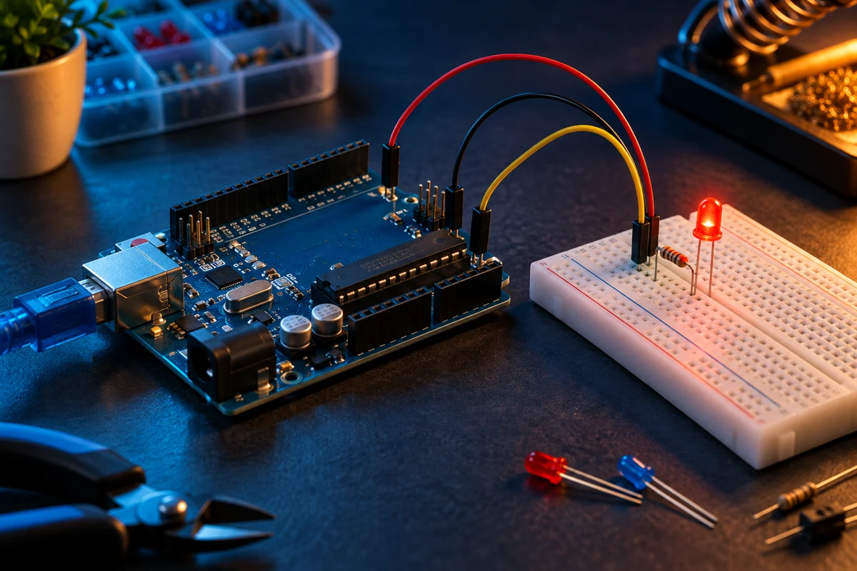
Breadboard, LED and resistor basics
Understand connected rows, LED polarity and why every LED needs a resistor.
A solderless breadboard connects groups of holes internally. The centre trench separates the two halves. Power rails may be split midway; use a continuity meter or the board documentation to check them before building.
An LED conducts primarily in one direction. Its long leg normally indicates the anode, and the flat edge normally indicates the cathode. Verify the part when leads have been trimmed. Put a resistor in series with each LED; a resistor can sit on either side of that LED.
For a typical red LED on a 5V Arduino UNO, 220 ohms is a useful starting value. Using a forward voltage near 2V, the estimated current is (5 - 2) / 220 = 0.0136A, about 14mA. Actual current varies with LED forward voltage. Check the board and LED ratings before changing values.
With USB unplugged, connect D8 to a 220 ohm resistor, the other resistor end to the LED anode, and the cathode to GND. Inspect the rows before powering the board. Try the Arduino Traffic Light project for three independently controlled LEDs.
Troubleshooting: disconnect power, check polarity, check for a misplaced wire, and confirm the ground connection. Never connect an LED directly between a GPIO and ground without a current-limiting resistor.
Reference: https://docs.arduino.cc/built-in-examples/basics/Blink/