

Arduino Traffic Light
Build a three-colour signal and learn digital outputs, LED polarity and current-limiting resistors.
Steps
Prepare the breadboard
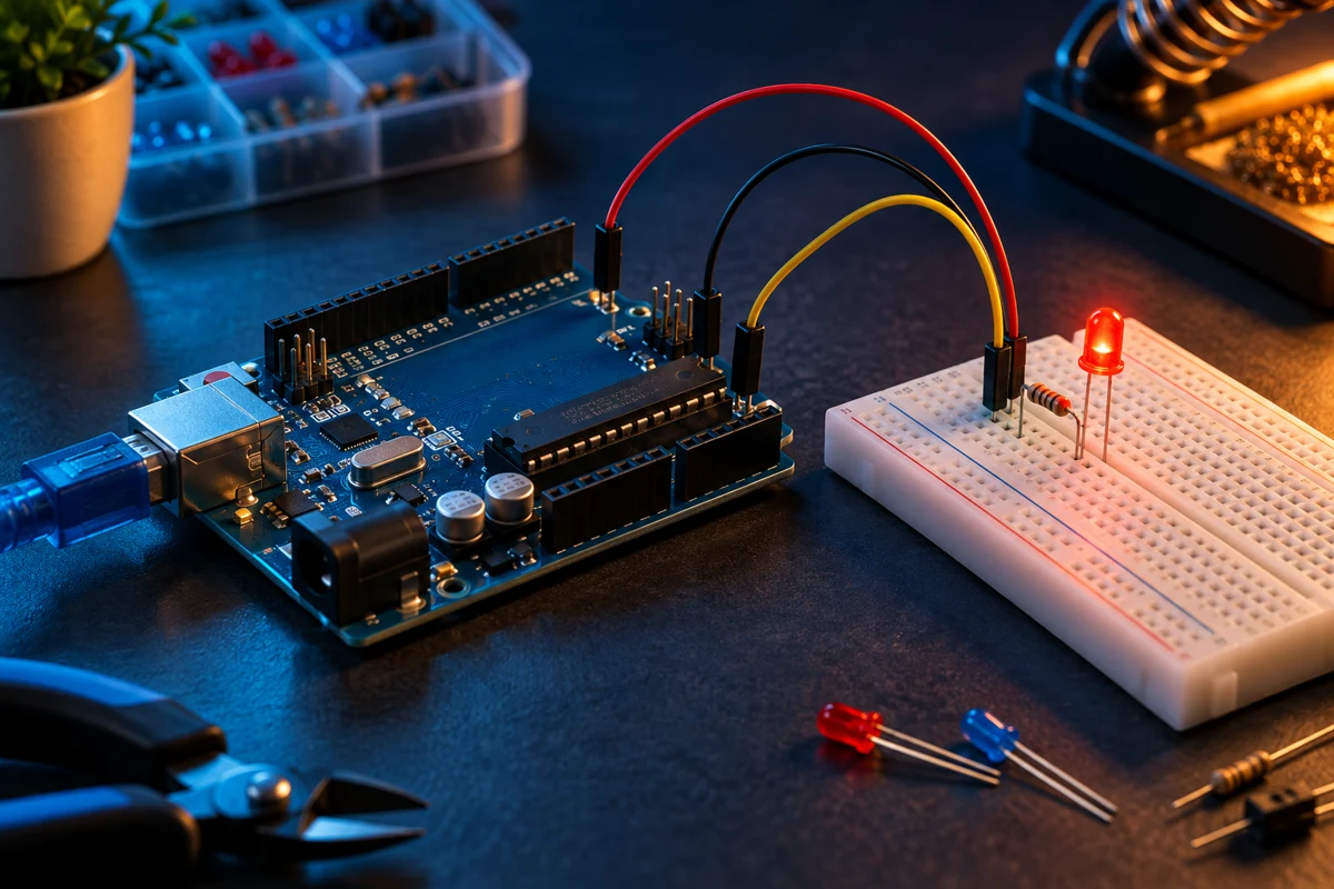
Unplug USB before wiring. Place red, yellow and green LEDs across separate breadboard rows. The long leg is normally the anode; confirm the flat edge marks the cathode.
Wire each LED
Connect D8 through its own 220 ohm resistor to the red LED anode, D9 through a second resistor to yellow, and D10 through a third resistor to green. Connect every cathode to UNO GND. Never share one resistor between LEDs.
Upload the sketch
Connect the UNO by USB, select Arduino UNO and the correct port, then upload. Red stays on for 3 seconds, green for 3 seconds, then yellow for 1 second.
Check and experiment
If an LED stays dark, unplug USB and check polarity and row connections. Change the delays to adjust timing. This demonstration is for a tabletop model.
Code
const byte RED = 8, YELLOW = 9, GREEN = 10;
void show(byte led, unsigned long ms) {
  digitalWrite(RED, LOW); digitalWrite(YELLOW, LOW); digitalWrite(GREEN, LOW);
  digitalWrite(led, HIGH); delay(ms);
}
void setup() {
  pinMode(RED, OUTPUT); pinMode(YELLOW, OUTPUT); pinMode(GREEN, OUTPUT);
}
void loop() { show(RED, 3000); show(GREEN, 3000); show(YELLOW, 1000); }