

Touch-Controlled LED
Tap a capacitive pad to toggle a green LED, using stable input detection and one action per touch.
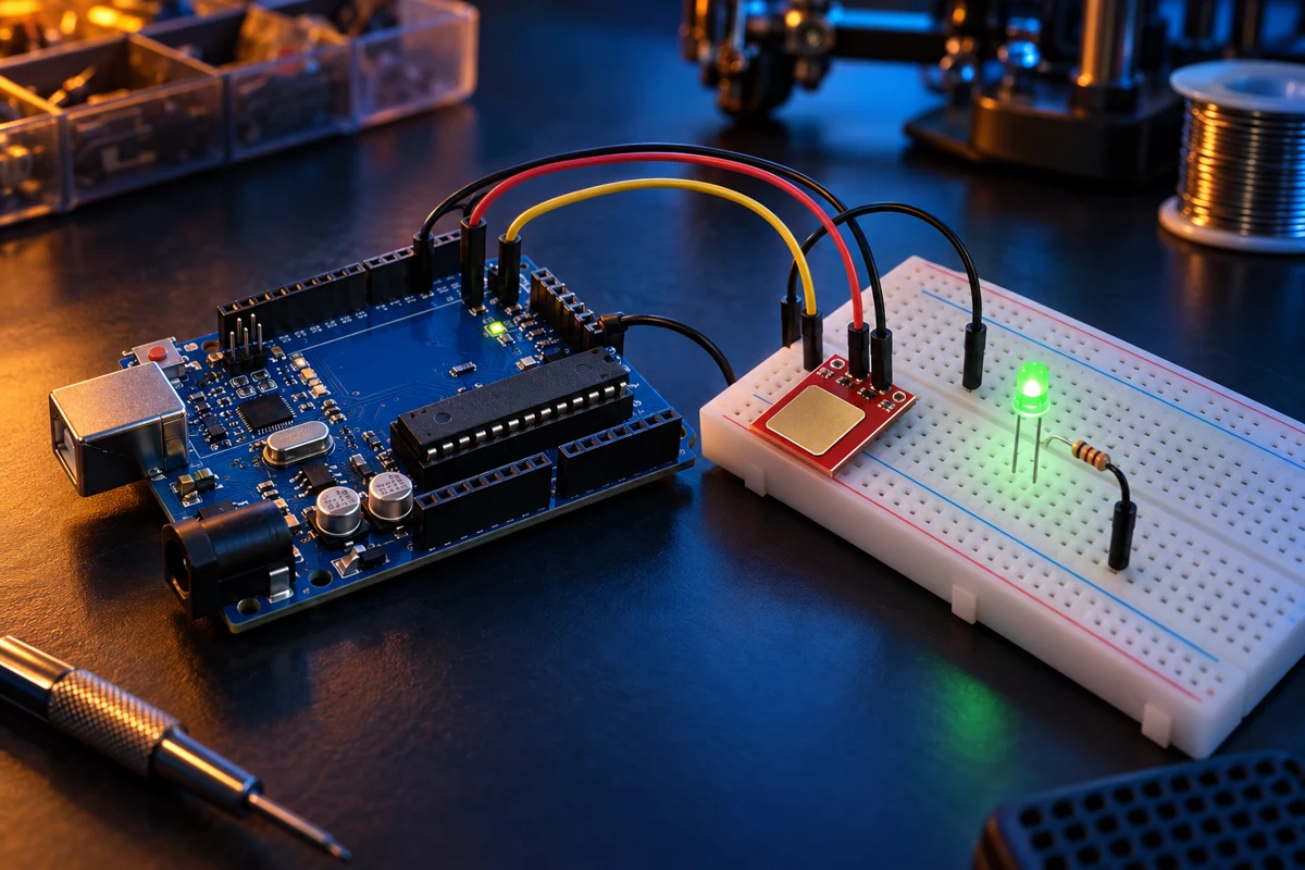
Steps
Check the touch module mode
Use a TTP223 module in momentary, active-HIGH mode: OUT is LOW when idle and HIGH while touched. Module solder bridges may select toggle or active-LOW modes. Confirm your module configuration before using this sketch; adjust TOUCH_ACTIVE for active-LOW operation.
Wire the touch sensor
With USB unplugged, connect TTP223 VCC to UNO 5V, GND to GND and OUT to D2. Use the PCB pin labels rather than assuming a universal pin order. Do not connect OUT directly to an LED load.
Wire the indicator
Connect D8 through a 220 ohm resistor to the green LED anode and its cathode to UNO GND. All parts share ground. Upload the sketch; leave the touch pad untouched during the two-second startup calibration period.
Test touches and releases
Tap the pad: the LED turns on. Hold a finger on it: the LED keeps its state. Release and tap again: the LED turns off. The sketch requires a stable signal for 30ms and reacts only to a newly detected touch. If behaviour differs, check the module polarity and whether it is in hardware toggle mode.
Code
#include <stdint.h>
const byte TOUCH = 2, LED = 8;
const int TOUCH_ACTIVE = HIGH;
const uint32_t STABLE_MS = 30;
bool ledOn = false;
bool lastRaw = false, stableTouch = false;
uint32_t changedAt = 0;

void setup() {
  pinMode(TOUCH, INPUT);
  pinMode(LED, OUTPUT);
  digitalWrite(LED, LOW);
  delay(2000); // Leave the pad untouched during calibration.
  lastRaw = digitalRead(TOUCH) == TOUCH_ACTIVE;
  stableTouch = lastRaw; // Ignore a touch already held at startup.
  changedAt = millis();
}

void loop() {
  uint32_t now = millis();
  bool raw = digitalRead(TOUCH) == TOUCH_ACTIVE;
  if (raw != lastRaw) { lastRaw = raw; changedAt = now; }
  if ((uint32_t)(now - changedAt) >= STABLE_MS && raw != stableTouch) {
    stableTouch = raw;
    if (stableTouch) {
      ledOn = !ledOn;
      digitalWrite(LED, ledOn ? HIGH : LOW);
    }
  }
}