

Touch-Controlled Servo Positions
Use a momentary touch pad to alternate an unloaded SG90 between two angles, with release-to-rearm input handling.
Steps
Gather power and signal parts
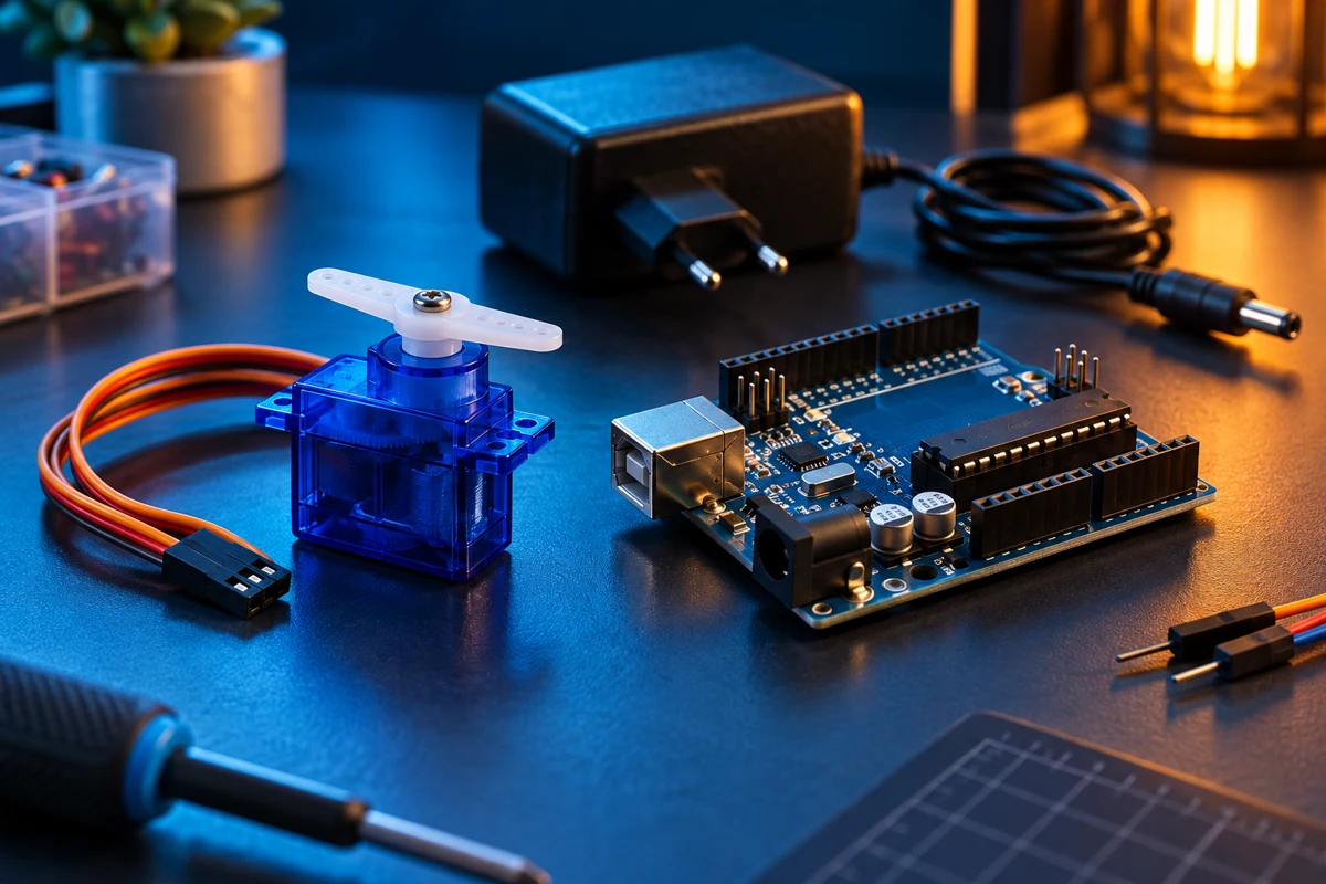
Use a UNO, a TTP223 touch module in active-HIGH momentary mode, an SG90 and a separate regulated 5V servo supply. The linked 5V 2A adapter still requires a matching barrel breakout/connector and suitable power wiring, which are not included in the linked parts list. Verify adapter polarity before connection. Start without a mechanical load.
Wire the touch input
With all power disconnected, connect TTP223 VCC to UNO 5V, GND to UNO GND and OUT to D2. Use the module's labels. TTP223 boards may be configured for toggle or active-LOW behavior; this sketch requires output LOW while released and HIGH while touched. Test this first before connecting servo power.
Wire the servo supply separately
Connect the servo signal, usually orange/yellow, to UNO D9. Connect servo red to the external regulated 5V positive and servo brown/black to its negative. Join external supply negative to UNO GND. Do not join the external positive to the UNO 5V pin while UNO is USB powered. Never power a servo from a GPIO pin or send the adapter's 5V output into UNO VIN.
Upload the sketch
Install/use the Arduino Servo library, select UNO and upload. It starts at 20 degrees. Power the unloaded servo and keep fingers clear of the horn. Serial Monitor uses 115200 baud. A stable released touch input arms the next activation; an input already HIGH at boot will not cause an extra toggle.
Test one event per touch
Touch once to move to 100 degrees, release for at least 30 ms, then touch to return to 20. A held touch must not repeatedly alternate the servo. The sketch filters short output changes; it does not add a timed servo movement profile. Mechanical travel and printed angle may differ on inexpensive servos.
Check power and travel
If the UNO resets or the servo chatters, disconnect power and inspect polarity, supply capacity, connector fit and the common ground. Keep wires short. Do not force the horn into an obstruction. Narrow the angle range if your servo approaches its physical stop; stall current can be much higher than unloaded current.
Code
#include <Arduino.h>
#include <Servo.h>
Servo arm;
const uint8_t TOUCH = 2, SERVO_PIN = 9;
const uint32_t STABLE_MS = 30;
bool rawState = LOW, stableState = LOW, armed = false, open = false;
uint32_t changedAt = 0;
void setup() {
  Serial.begin(115200); pinMode(TOUCH, INPUT);
  rawState = stableState = digitalRead(TOUCH);
  changedAt = millis(); arm.attach(SERVO_PIN); arm.write(20);
  Serial.println("Release touch pad to arm. Touch once to move.");
}
void loop() {
  uint32_t now = millis();
  bool raw = digitalRead(TOUCH);
  if (raw != rawState) { rawState = raw; changedAt = now; }
  if (uint32_t(now - changedAt) < STABLE_MS) return;
  if (rawState == LOW) armed = true;
  if (rawState != stableState) {
    stableState = rawState;
    if (stableState == HIGH && armed) {
      armed = false; open = !open; arm.write(open ? 100 : 20);
      Serial.println(open ? "Position: 100 degrees" : "Position: 20 degrees");
    }
  }
}